GamePi Zero
I love retrogaming and hardware projects. To gather the best of 2 worlds, I decided to create my own console.
It is a little coincidence that I decided to finish this project on the 30th anniversary of the original Nintendo Gameboy, but here it is. You get it, I won’t write about information security today.
First of all, I am just an electronics amateur and the solutions I found to assemble a DIY GameBoy are mine. So don’t take my word as it, some solutions may be bad but worked for me. That said, let’s begin the fun part.
The project
Many years ago, the little me had a GameBoy Color as a birthday present. It still works fine but with some annoying details:
- The batteries of my game cartridges are dead and thus it is impossible to save a game and power the console off,
- The screen of my GameBoy Color is not backlit.
I could have found direct solutions to remediate the problems directly on my GameBoy Color unit but I found funnier and more instructive to assemble one around a Raspberry Pi Zero W.
I am far from the first one to do it and followed some advice from other makers but I took the decision to learn a maximum from it from taking my own decisions about it design.
I wanted the following requirements:
- 3-D printed case for the DIY aspect,
- Autonomous power (usable on the go) with at least 3 hours of battery,
- Possibility to play games from other platforms,
- WiFi and Bluetooth connectivity to extend the keypad of the GameBoy and allowing to access the system without having to tear down the console.
The components
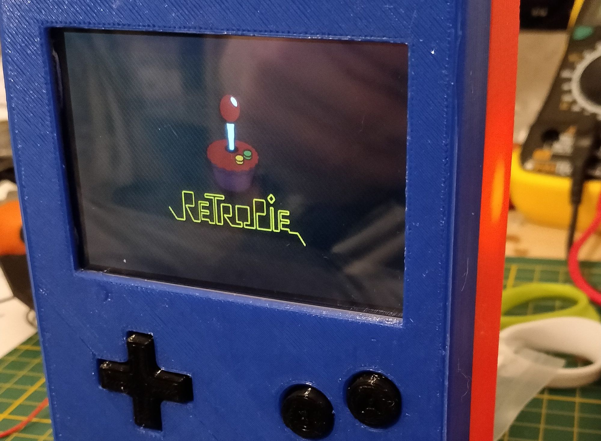
The main core is constituted of a Raspberry Pi 0 W, the Wireless-enabled version of the Raspberry Pi 0 micro computer. It is loaded with the infamous Retropie, a retro gaming bundle designed for the Raspberry Pi. It is not difficult to configure for a standard Raspberry Pi, but I recommend to use a full-size screen (like a 24′ monitor) to see something in the console parts of the configuration.
You can configure it with a simple keyboard (don’t forget a mini-HDMI to HDMI cable and an OTG USB adapter as the connectors are made to be the tiniest possible) on a regular power source. Map the emulator with the keyboard, it makes the next steps more complicated to configure if you use a regular game controller.
Next, you will need something to act as the keyboard when a user interacts with the games. I chose to use the infamous Teensy 2.0 due to its small size, programming ease (with Arduino IDE) and built-in HID features.
I programmed it as a keyboard and didn’t forget to add some extra buttons to allow a hotkey (triggering special commands in EmulationStation and retroarch).
Using the keyboard library check for the falling and raising edges of button signals to emulate button press and release. You will need to catch both to allow buttons to act as they are pressed on the whole process. You may also want to use the Bounce library to avoid accidental repetition of an input when a push button is released.
Using the internal pull-up resistors of the Teensy, it is easy to connect the buttons. Just connect the button to the corresponding IO pin and connect the other side to the ground.
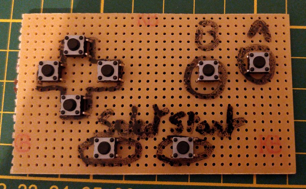
The perfboard supporting the buttons can be easily enclosed after the soldering. Unfortunately I was not able to solder the Teensy on it but it should be possible.
After that, the Teensy can be connected to the Raspberry Pi and will act as a keyboard.
The integrated screen is mounted on the Raspberry Pi’s GPIO pins only to get powered by it. I glued it to the case with some epoxy glue (i may add an epoxy protection layer in the future). It is connected to the Raspberry Pi with HDMI for the display. But the screen is mounted upside down in my case. So I had to inverse the screen display.
This can be achieved by telling the Raspberry Pi to rotate the display:
sudo nano /boot/config.txt

# Add or edit the following line
display_rotate=2 # Rotates 180°
That done, I added 2 speakers in a stereo configuration . They are linked to a jack female connector that can also allows headphones connection. I found this connector was a piece of magical engineering. Rather than detecting by software that a headphone has been connected, the signal is simply cut by opening physically the circuit when connecting the male jack connector from the headphones.
The screen I integrated had also a jack connector that I hacked to get the signal to the speakers (initially, the Raspberry Pi is outputting its sound to the HDMI connection). But I did a mistake here. I assumed that the signal was amplified enough for the speakers and that I did not need to add any subsequent amplification. I was wrong and the sound coming from the speakers is barely audible.
I may fix this issue later but I mostly use the headphones, that work fine.
With all these pieces together, I missed only one feature. The power line.
To give the Raspberry Pi 0 W a steady 5.20V power supply, I used an LM2596 DC-DC buck converter which does its job quite well. Even if the voltage supplied by the batteries drops as they discharge.
The output of this converter is directly connected to the Raspberry Pi input (don’t forget to set the right output voltage before connecting both or you’ll probably fry the Raspberry Pi). On its input side, I added a simple switch to power it (and all the system) on and off.
This input comes from a 3S li-ion Battery Management System that outputs (when the batteries are fully charged) 12.6V and can support a current draw of 20A (which I highly doubt I will reach one day). The batteries are simply connected to this BMS for their protection and placed in battery holders to allow an easy disassembly to allow recharge outside the console (I have not circuitry to allow battery charging).
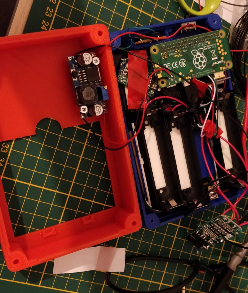
Nearly everything is assembled. We see the BMS in the down right corner of the image and the DC-DC buck converter in the red case part
Having all components working together, I finished to design the case, buttons included, in FreeCAD before printing it on my home 3D printer (5 hours roughly for the front case and also 5 hours for the back case). I added at last a battery cover (1 hour of printing) to protect the 18650 cells that are inserted in the battery holders.
Conclusion
After using it during a week, this project definitively fulfilled my needs for retro-gaming.
The real autonomy is around 4 to 5 hours. A bit better that I expected, it may be improved if I find a simple solution to cut the WiFi antenna. But using 18650 batteries is maybe not the best idea I had because the console’s thickness is about 50mm. A bit much to be hold for a long time, that limits the gaming sessions length.
Moreover, the 3D-printing is giving exactly the DIY feeling I wanted. Really a cool project 🙂
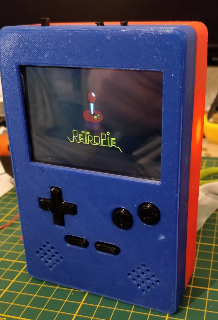
And here is the fully assembled bad boy: